

The Valve Assembly
The purpose of the valve assembly is to direct HP air to the top of the power piston during the downstroke, and to the bottom of the power piston during the upstroke. It must also open the bottom of the power cylinder to the atmosphere during the downstroke (and vice versa), to exhaust any remaining compressed air and to keep pressure from building up as the power piston moves down. This is shown schematically in the diagram above
There are many possible ways to design a valve piston, but a common type, the 'spool', is shown in the figure above. The spool is a narrow cylinder with wider cylinders on either end. The narrow part of the spool allows air to pass from the HP supply to the appropriate side of the power piston, which the larger part blocks HP air from the exhaust ports. As you might guess, it is the length of the larger parts of the spool (and their relationship to the intake and exhaust ports) that determine much of the timing of the engine.
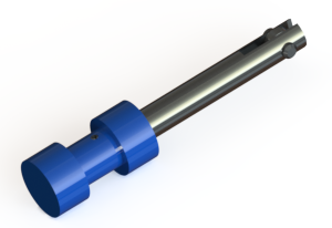
The figure at right shows a rendering of the valve piston assembly used in the Rowan prototype air engine. The spool is made of acetal turned on a lathe, and the rod is polished mild steel. There is a small ball bearing at the end of the rod which transmits the forces from the rocker assembly, to be described later.
The animation above may help you to visualize the role of timing in the air engine. Press 'play' and watch the valve and power pistons move through their cycles. The light pink areas represent high pressure air, and the light blue areas symbolize low pressure (atmospheric) air. Observe that HP air moves to the top of the power piston when the right-hand intake port is opened by the valve, and that HP air moves to the bottom of the power piston when the left-hand intake port is opened. It is important to remember that this is just an animation, not a physical simulation. There are many settings of the phase angle for which a real engine would not work at all, but the animation just keeps chugging along! The goal of this animation is to help you find a range of phase angles that would work on a real engine.
The slider at the left changes the angle between the power crank and the valve crank. If the slider is set to '0', the power piston and valve piston are said to be 'in phase', that is, they reach the top and bottom of their strokes at the same time, and the cranks maintain the same angle. Try setting the phase to '180°' or '-180°'. At this setting the power piston reaches the top of its stroke when the valve piston is at bottom. In this setting, the pistons are said to be 'out of phase'.
In a real, working air engine, the phase is not 0° or 180°, but somewhere in between. As a first guess, try setting the phase angle to positive 90°. Now watch the flow of high-pressure and atmospheric air. You can see that high-pressure air flows to the top side of the power piston when it is on its upstroke, which would have the effect of stopping the power piston in its tracks! Similarly, the HP air flows to the bottom of the piston on its downstroke. Clearly, this is not a workable engine.
Now try a setting of negative 90°. Here the situation is much better - HP air flows to the top of the piston at the beginning of the downstroke and to the bottom of the piston at the beginning of the upstroke. This would appear to be a reasonably successful design. In fact, we can use it as a starting point as we further refine the design of the valve piston in a later section.
