

Air Engine Timing Design
Our next task is to design the valve piston to achieve the proper engine timing. The diagram above shows a schematic of the air engine, with the 'spool' valve replaced by a traditional steam engine valve. We will go through the exercise of designing this valve train first, and use the lessons learned here to design our own spool valve. The main factor that determines engine timing is the relationship between power crank angle and valve crank angle as shown in the diagram above. The valve crank usually 'leads' the power crank by a specified angle, which we will determine in the procedure that follows.

An enlarged view of the valve is shown in the diagram above. The intake ports connect with the top and bottom of the power cylinder. The 'lap' and 'exhaust lap' determine how much larger the valve seat is than the intake port it covers. There are a few important features to note:
- Lap: the amount that the valve overlaps the intake port on the high-pressure side.
- Exhaust lap: the amount that the valve overlaps the intake port on the exhaust side.
- Admission angle: this is the power crank angle at which HP air begins to enter the intake port (and flow to the power cylinder.) This angle is usually less than zero, since we would like HP air to begin to enter the power cylinder a little before the power piston has reached TDC.
- Cut-off angle: The power crank angle at which HP air stops flowing to the power cylinder.
- Release angle: The power crank angle at which air begins flowing from the power cylinder to the exhaust port. The name 'release' is used because any remaining pressure in the power cylinder is 'released' to the atmosphere.
- Compression angle: The power crank angle at which air stops flowing from the power cylinder to the exhaust port. The compression angle is usually slightly before TDC, so the motion of the power piston beyond this point has the effect of compressing the remaining air inside the power cylinder.
 |
 |
| Admission | Cutoff |
 |
 |
| Release | Compression |
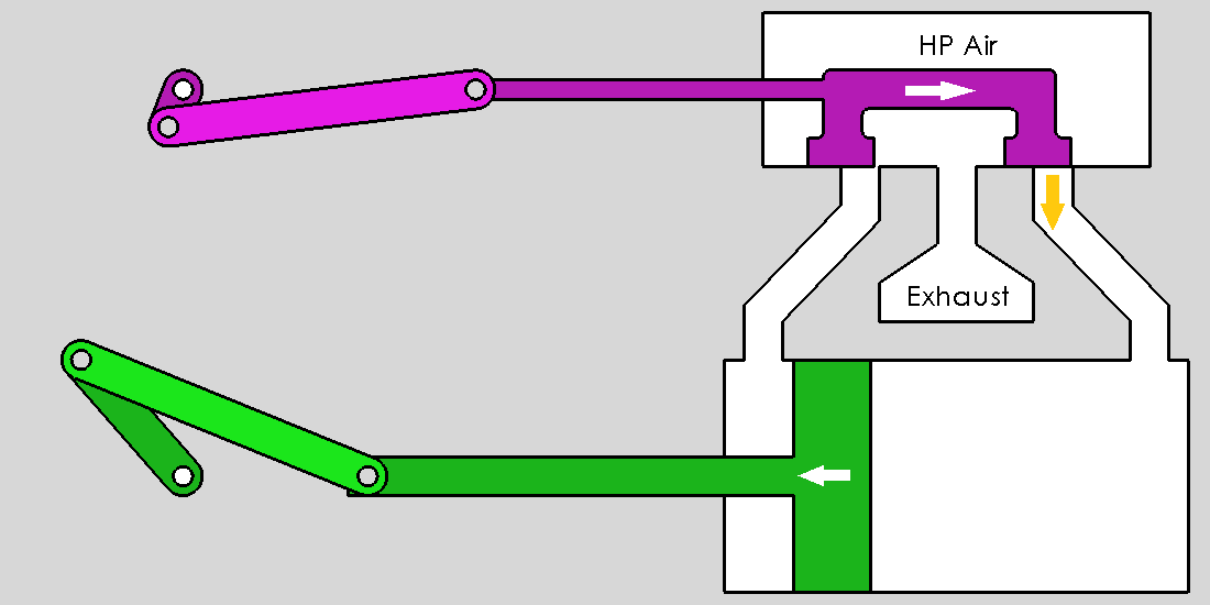
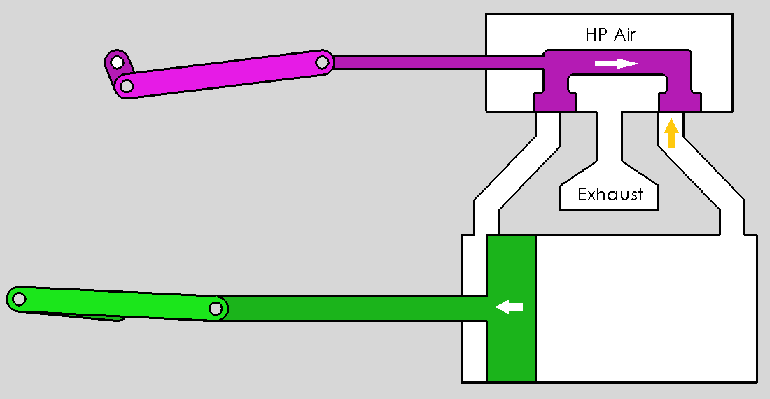
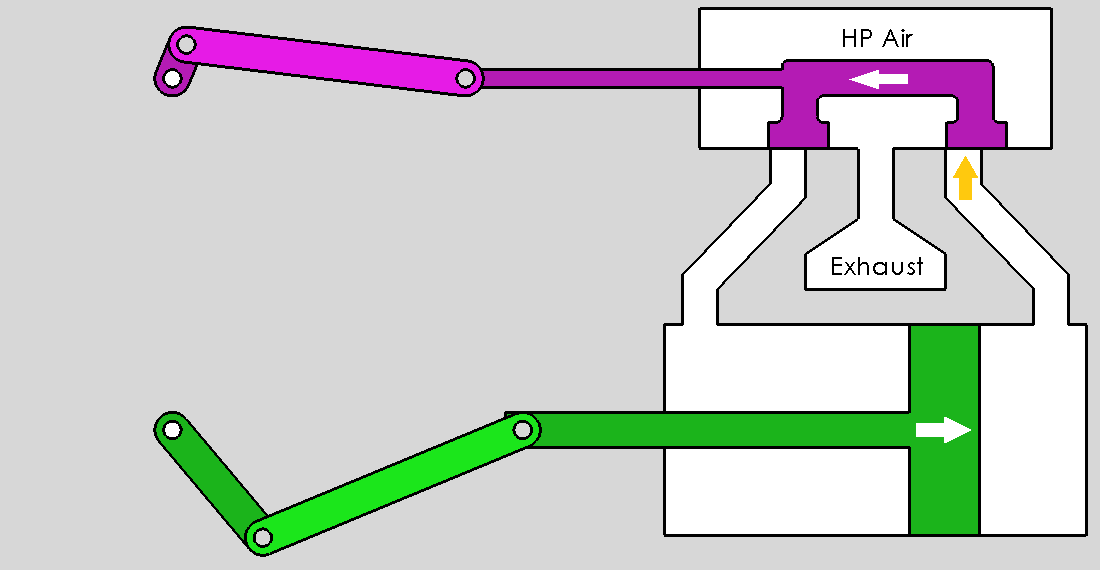
The cartoon above shows the four stages of the air engine in more detail. The intake port begins to open to the HP air supply at admission. The HP air supply is stopped at cutoff. The air in the power cylinder is opened to the atmosphere at release. And finally, the intake port is sealed during compression. Note that the intake port is also sealed between cutoff and release; the HP air is allowed to expand (and do work on the piston) during this time.
The Reuleaux Diagram
You will note that there are several design variables in the list above. To fully determine the dimensions of the valve piston, we need specify only four: the valve travel, the admission angle, the cut-off angle and the release angle. The compression angle, lap and exhaust lap will be determined from these using the Reuleaux diagram outlined below.
The procedure in the following section is a modified version of the Reuleaux diagram, invented by Franz Reuleaux, a German kinematician who lived in the nineteenth century. In the pre-computer era, it was handy to have a purely graphical method for designing steam engine linkages. The Reuleaux diagram is still useful today, although we normally use a CAD package (such as AutoCAD or SolidWorks) to draw it. To help illustrate the procedure, we will use numbers from the design of the Rowan air engine. This engine has a total valve travel of 0.52in, with an admission angle of -5°, a cut-off angle of 130° and a release angle of 170°.
 |
 |
| Step 1 | Step 2 |
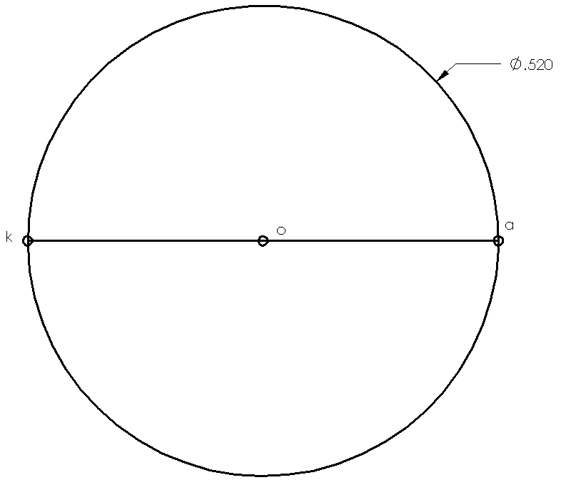
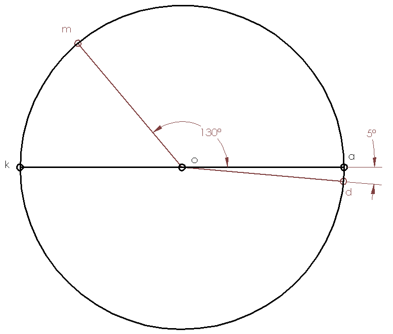
Step 1: Draw a circle centered at point o of diameter Δ, where Δ is the total valve travel. Label the points on either side of the circle a and k. In our example, the valve travel is 0.52in, so that is the diameter of the circle.
Step 2: Now draw a line from point o at an angle θa, where θa is the admission angle. Draw another line from point o at an angle θc, the cut-off angle. Label the new points d and m. In our example, we have an admission line at -5° and cut-off line at 130°.
 |
 |
| Step 3 | Step 4 |
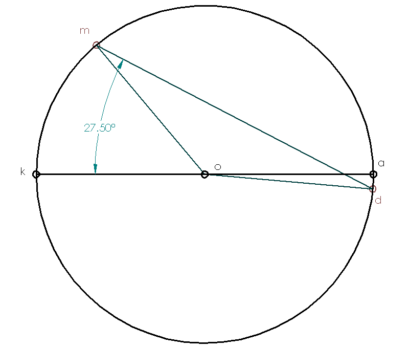
Step 3: Measure the angle of the line dm. Since the valve is at the middle of its stroke when the valve crank is at 90°, the total angle between valve crank and power crank is 90° + 27.5° = 117.5° in our example.
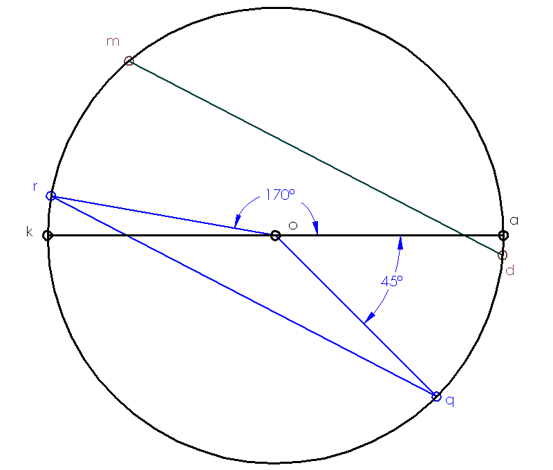
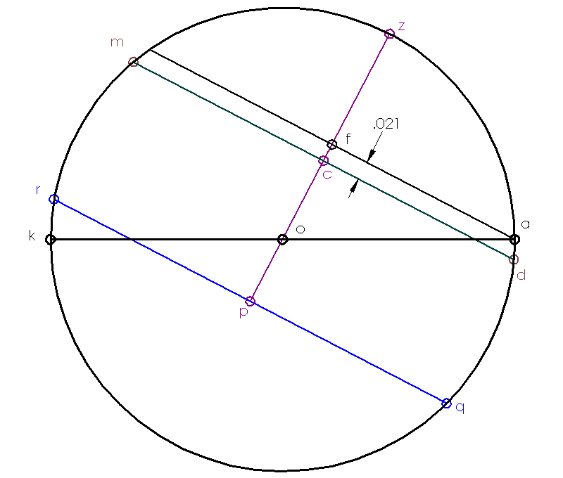
Step 4: Now draw a line from point o at the release angle, θr and label the new point r. Draw a line parallel to dm through point r. Label the point where it reaches the other side of the circle q. The angle that line oq makes is the compression angle (-45° in this example.)
 |
 |
| Step 5 | Step 6 |
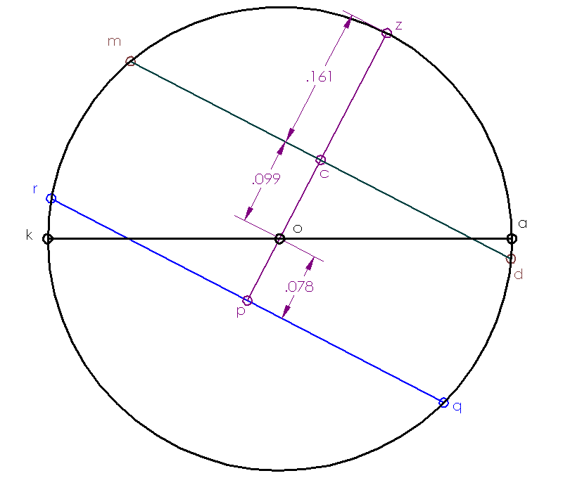
Step 5: Draw a line pz perpendicular to dm and passing through point o. The distance oc is the lap and the distance op is the exhaust lap. As an added bonus, the distance cz is the maximum port opening!
Step 6: Finally, draw a line parallel to dm through point a. The distance cf is the lead. This is the distance that the intake port is open when the power piston is at TDC.
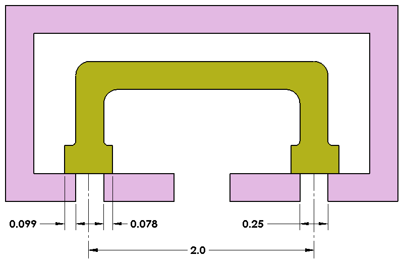
Now let us take the dimensions we measured in the Reuleaux diagram and translate them into a working valve. In the diagram above, the ports are each 0.25 inches in diameter and are spaced 2.0 inches apart. Consider first the left port. The lap (0.099in) gives the amount that the valve extends beyond the port on the left side, and the exhaust lap (0.078in) gives the amount of extension on the right side. The total width of the valve seat is 0.099in + 0.25in + 0.078in = 0.427in.

Finally, let us see what we need to do to convert the valve we designed using the Reuleaux diagram for use with the 'spool' design and the rocker linkage. Recall that the rocker linkage forces the valve to be 180° out of phase with the power piston; that is, the valve moves up as the power piston moves down, and vice versa. In addition, the port arrangement is different in the spool design, as shown in the figure above. In the Reuleaux design, the left intake is open to HP air when the valve moves to the left, while in the spool design the left intake is connected to the exhaust when the valve moves to the left. Therefore, the action of the spool valve is exactly 180° out of phase with that of the Reuleaux valve. The net effect of both differences is that we can use the same phase angle as we determined earlier, but the lap and exhaust lap must exchange places (the exhaust lap is now on the outside of the spool). The Reuleaux diagram works for the spool valve design - try it yourself!
