Flow Control to the Air Motor
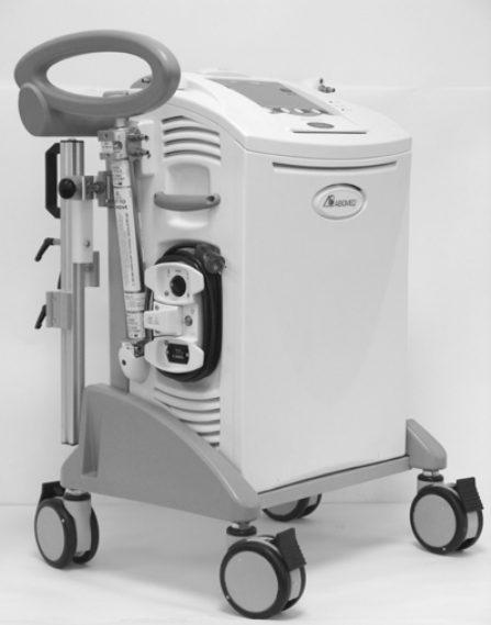
For safety and efficiency speed control is essential for all dynamic mechanical systems . Originally our strategy was to control air engine speed using a stepper motor and a control valve. However, our initial prototyping work revealed this approach would not provide the resolution or granularity that we sought. In other words the flow changes were too abrupt or too large when control inputs were given. As result we explored discrete valves systems like those used to regulate pressure in Abiomed's AB5000 (Figure 1).


Discrete Flow Valve Design
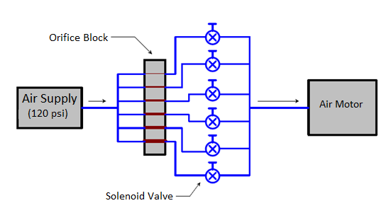
Our goal was to design a flow control system that offered significant flow control resolution . Figure 3 shows a schematic of a discrete flow control system. The air supply is fed into individual on/off solenoid valves that are connected to flow paths of different diameters. By choosing four separate valve–flow path pairs, there are 15 possible discrete flow levels possible in this configuration. This value comes from this equation found in statistics[1]:
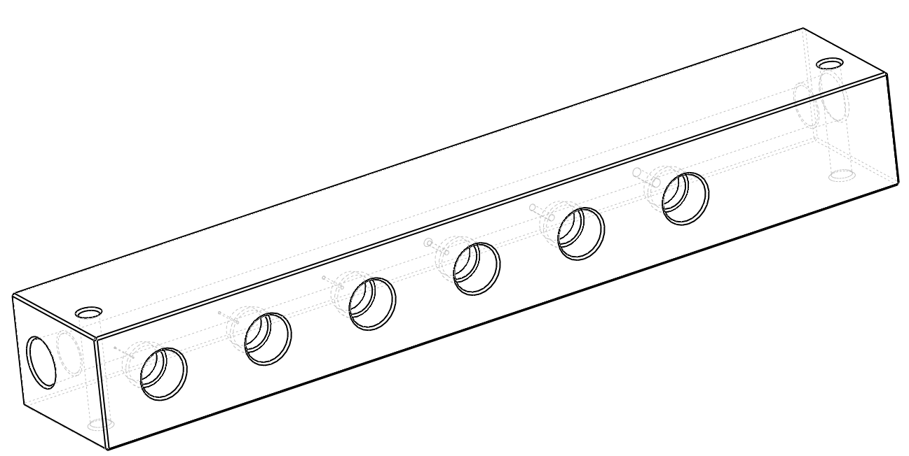
\begin{equation} C(n,r)=\frac{n!}{(n-r)!(r!)} \end{equation}where C (n,r) is the number of combinations, n is the number of valves available, and r is the number of valves open at one time. If you sum all the combinations starting with a fixed number of valves available and go from one valve open to all valves open you will have the total number of potential combinations possible. Our first design involved six different flow valve–flow path pairs providing substantial flow control with 63 combinations of flow configurations. Initial flow drill sizes for each flow path were then estimated by this sequence where A0 is the cross-section flow area of the connector: A0/63, 2A0/63, 4A0/63, 8A0/63, 16A0/63, 32A0/63. Figure 3 shows the initial manifold we have built that includes the flow paths that are coupled to bank of six on/off solenoid valves.

To predict the maximum flow through the assembly compressible flow equations that assume frictionless ideal gas behavior were used. The equation used to calculate the maximum flow (kg/s) was [2]:
\begin{equation} \dot{m}_{max}=A_0\left[k{\rho}P\left(\frac{2}{k+1}\right)\left(\frac{k+1}{k-1}\right)\right]^{1/2} \end{equation}where A0 is the fitting minimum cross sectional flow area, k is the ratio of specific heats for air, ρ is the density of air upstream of the flow path, P is the absolute pressure of air upstream of the flow path. Eq. (2) assumes that the air flow is 'choked', meaning that the velocity of the air through the flow paths cannot exceed the speed of sound. This occurs when ratio of downstream pressure to upstream pressure is 0.528 or smaller[3]. In our case, using an inlet pressure of 100 psig and an outlet pressure of 14.7 psia results in an absolute pressure ratio of 0.128, definitely a case of choked flow. Under these conditions, with 5/32in. A0 , the predicted maximum flow was 22.75 g/s.
To predict the flow rate with different discrete valve-flow paths open, we took the maximum predicted flow (22.75 g/s) and divided it by A0 and then multiplied that mass flux (1.85x10⁶ g/s/m^2) by the corressponding flow areas of the open discrete valve-flow paths. In our first design using a #80 drill bit (0.0135 in) that approximates A0/63, the smallest mass flow increment was predicted to be 0.17 g/s. This was exactly the kind of flow resolution we were seeking.
An excellent example of a MATLAB user interface designed by the "Dream Team" is seen in the Youtube video below. The Dream Team consists of Nick Dow, Brent Boszczuk, Mitchell Henthorn and Elliot Schwartz. Great work, fellows!
[1]Mathematics website: http://www.mathsisfun.com/combinatorics/combinations-permutations.html, Accessed 8/20/13.
[2] White, F.M., Fluid Mechanics, 6th edition, McGraw-Hill, New York, NY, 2008, pg. 617
[3] Munson, B.R. et al., Fundamental of Fluid Mechanics, 6th edition, Wiley, New York, NY, 2009, pg. 598.

