
The Power Assembly
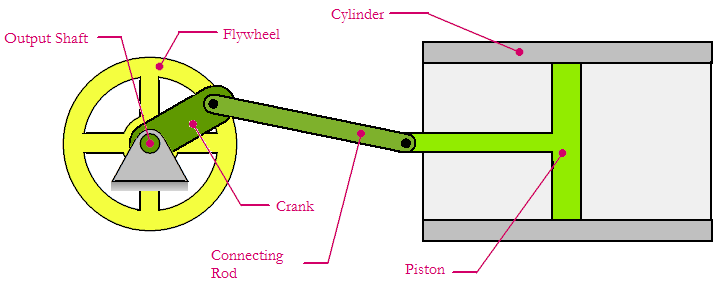
A schematic diagram of the power assembly is shown in the figure above. Many of the items will be familiar to those acquainted with automotive engines, including the piston, cylinder, connecting rod, crank and flywheel. We will describe each of these items in some detail below, and also provide some (very rough) design guidelines. If you want to skip ahead to a more detailed design procedure, please see the Reuleax Diagram page.
Power Piston
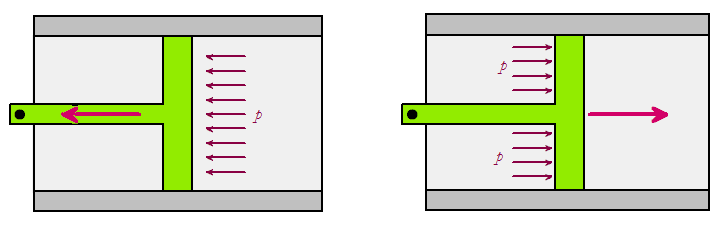
The figure above shows the power piston in isolation. In the left diagram, high-pressure air forces the piston to move downward; this is called the 'downstroke'. The right diagram shows the upstroke. While the functioning of the piston is the same as in an automotive engine, you have probably noticed that the piston is 'dual-acting'; that is, it is powered on both the up- and down-strokes. The resulting motion is much smoother than if the piston were powered on only the downstroke, as in an automotive engine. It is impractical to have a combustion chamber on both sides of a piston in an automotive engine, so multiple pistons are used to create smooth rotary motion.
Connecting Rod
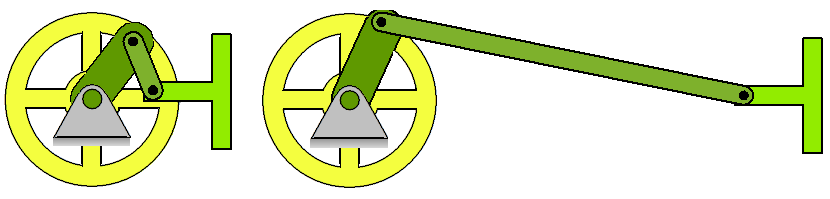
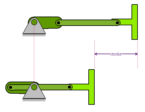
The connecting rod attaches the power piston to the crank. It is simply a link, usually made of aluminum, with pins at either end. The pins may be mounted in tiny ball bearings if lower friction is desired. The major design constraint for the connecting rod is that it not be too long, or too short. As shown in the figure above, a connecting rod that is too short will 'bind up' when the crank is nearly vertical. Conversely, a connecting rod that is too long will require superfluous material to house the cylinder and output shaft bearings. In addition, larger connecting rods create more moving mass, often leading to vibration problems. Trying to overcome this problem by making the connecting rod long and thin can lead to buckling problems. In summary, the designer should make the connecting rod as short and light as possible, while avoiding the binding problem shown in the figure top left.
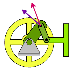
Another consequence of a short connecting rod is shown in the figure at right. Since the rod has pin joints at either end, the force it transmits must be parallel to the rod; this force is shown in pink. The goal of the connecting rod, however, is to produce a torque on the crank. The torque-producing force is perpendicular to the crank, and is shown in purple. The component of the connecting rod force that is not aligned with the torque force is 'wasted', since it produces no torque (and increases friction in the bearings, in fact). There is most likely an optimal length for the connecting rod that minimizes the misalignment between connecting rod force and torque force, but I have not derived it. Reader input is welcome!
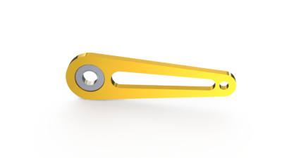
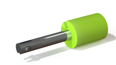
The figure at right shows a rendering of the connecting rod used in the Rowan prototype design. Note the 'lightening hole' in the center of the rod and the small ball bearing used to reduce friction with the crank pin. The connecting rod is made of aluminum cut using an abrasive waterjet CNC machine, but could also be lasercut in plexiglas.
The Crank
The crank transfers the back-and-forth motion of the connecting rod to the rotary motion of the output shaft. As you can see in the figure above, the crank also determines the total stroke length of the piston. As with the connecting rod, design of the crank is a compromise. A long crank will produce high torque (a good thing!) but will require a greater stroke length and will consume a larger amount of air per stroke (a bad thing!) The length of the crank is usually determined by the torque requirement for the engine, and is kept as small as possible
The Flywheel
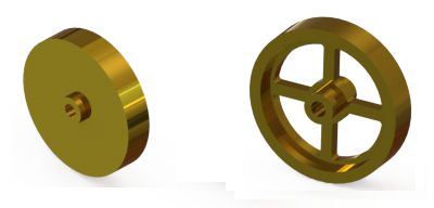
The flywheel is used to smooth out speed fluctuations in the output shaft caused by the pulses of compressed air against the faces of the piston. Without the flywheel, the output shaft would speed up suddenly when HP air was first admitted to the power cylinder, and then slow down as the air in the cylinder is allowed to expand. As we will see, this is especially true for designs with small cutoff ratios, where HP air is admitted to the cylinder during a small part of the stroke.
As with all other parts of the air engine, flywheel design is a compromise. If we make the flywheel too small, it won't have enough rotary inertia to smooth out the speed fluctuations. Conversely, an excessively large flywheel will make the engine respond sluggishly to desired changes in speed (as when the controller tells the engine to speed up from 1000rpm to 2000rpm). In any case, we should design a flywheel with as much rotary inertia as possible for a given mass.
This completes the overview of the power piston assembly. The next step is to examine the valve piston assembly in detail, which can be seen here.
