
Introduction
All of the power needed to propel a hybrid car forward is created by burning gasoline in an internal combustion engine (ICE). During some driving situations, the ICE may be connected directly to the wheels, and in others, it may charge the battery pack. In a Toyota Prius, it's likely that the ICE is performing both tasks simultaneously. Since all power is ultimately derived from the ICE, it is called the 'prime mover' in the hybrid system.
The air engine is the prime mover in the bench-scale hybrid powertrain. The job of the air engine is to convert the energy stored in compressed air to rotational motion at the output shaft. Since we are trying to produce a 'fuel-efficient' powertrain, we would like the engine to use compressed air as efficiently as possible. In addition, the speed of the output shaft must be roughly compatible with the rest of our hybrid powertrain. To summarize, the design goals for the air engine are:
- Convert compressed air energy to smooth rotational motion as efficiently as possible
- Speed of output shaft should be similar to rest of hybrid powertrain, between 500 and 2000rpm.
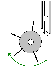
There are two major types of air engines: rotary and reciprocating. Rotary air engines use a turbine to convert the energy of high-speed air into rotational velocity. These engines are commonly seen in air tools, such as the air-powered impact drivers used in automotive repair shops. They are normally associated with high speed and low torque, and would need to be 'geared down' considerably to be useful in our application. A schematic of a rotary air engine is shown in the figure at right. A jet of compressed air is directed at the vanes of a turbine, which is forced to rotate. Of course, the torque output can be increased by increasing the size of the vanes, at the cost of a significant increase in compressed air consumption.
The reciprocating engine uses a crank to transform the up-and-down motion of a piston to rotational motion at the output shaft. The reciprocating engine we will develop here is modeled on the mechanism used in steam locomotives in the nineteenth century. Reciprocating engines are characterized by high torque and (relatively) low speed, and are very well-suited to the bench-scale hybrid powertrain
The Reciprocating Air Engine
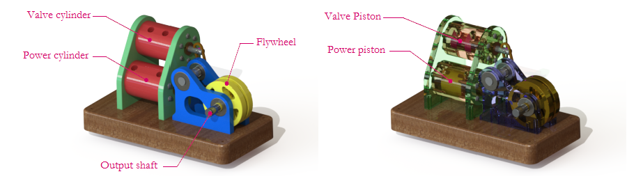
The air engine we describe here is modeled on a steam engine that might be found in an old locomotive. There are two main assemblies in the air engine, which will be described in some detail in the pages that follow. The first is the power assembly, which transforms the pressure energy of the compressed air into rotational motion of the output shaft. The second part is the valve assembly, which ensures that compressed air is applied to the correct side of the power piston at the proper time. Both of these assemblies must be precisely synchronized for the engine to work correctly.
The figure above shows two renderings of one possible air engine design. This engine has been built and tested extensively at Rowan, and has worked reliably for many years. Rowan Mechanical Engineering students design and build their own air engines every year in their Thermal-Fluid Sciences class, and the designs are often quite different than the one shown here. Air engine design leaves a lot of room for creativity!
Before diving into the details of the air engine design, you may find it helpful to watch the animation above. In this schematic, high-pressure air is shown in light pink, and low-pressure (atmospheric) air is shown in light blue. The valve piston is shown in bright pink, and the power piston is shown in bright green. As you can see, the valve piston diverts the high-pressure air to the top or bottom of the power piston, in order to push it up or down as needed. More specifically, the valve piston ensures that HP air is on the top side of the power piston during the downstroke and on the bottom side of the power piston during the upstroke. In watching the animation, it is easy to see how the timing and dimensions of the valve piston are critical to making a successful air engine. To learn more about the parts of the air motor, click on Parts of the Air Motor in the navigation bar. If you wish to jump ahead to air motor design, follow Air Motor Design in the navigation bar.
